Summer 2025 research recap
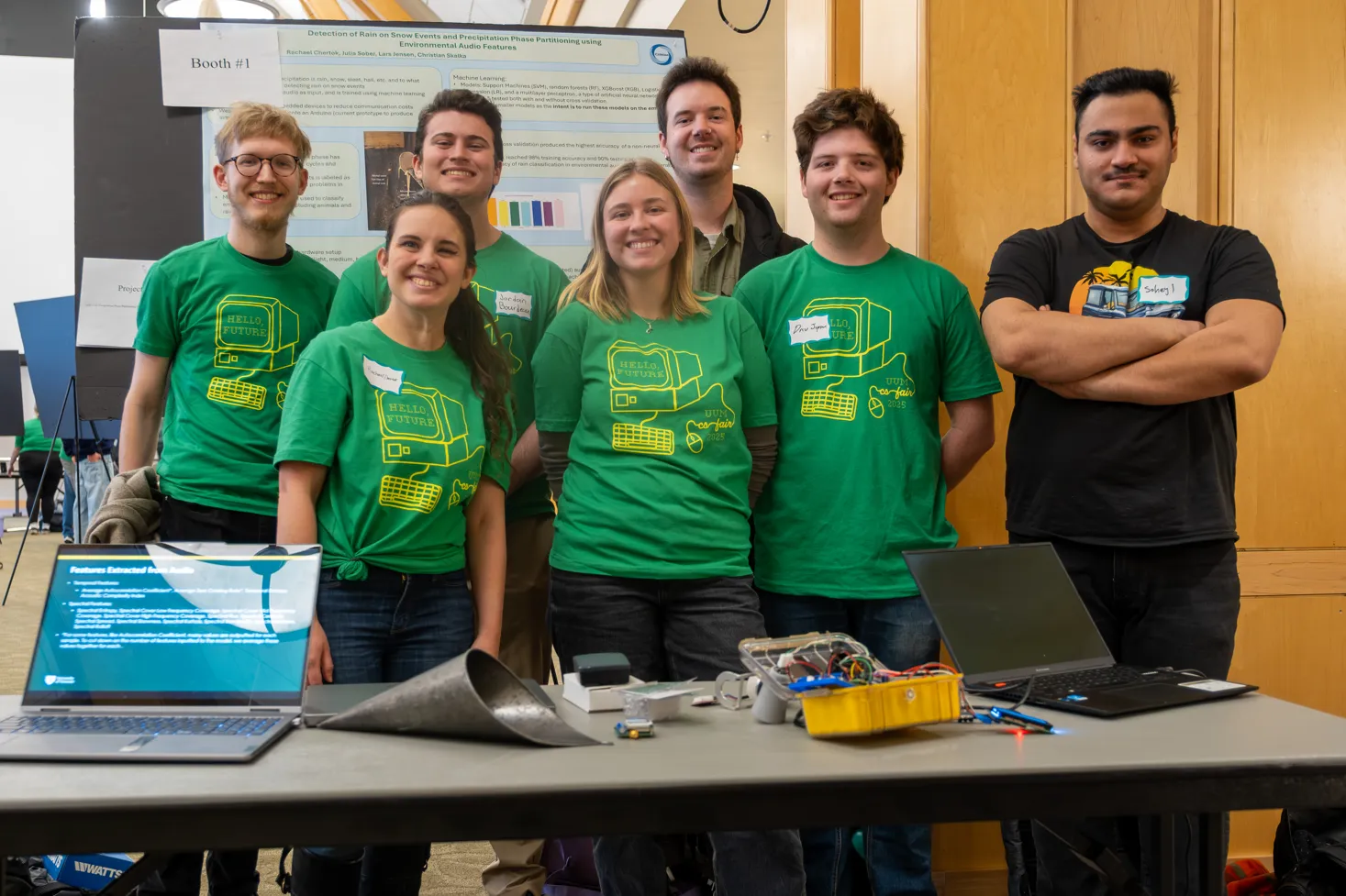
I had a fantastic summer working as a GRA (graduate research assistant) for a CIROH-funded project developing software for low-cost IoT sensor networks to perform near real-time precipitation detection and phase partitioning. During this time, our research group submitted the paper “Embedded IoT System for Acoustic Precipitation Phase Partitioning via Edge ML and MFCCs” to the IEEE Internet of Things journal. If you’re interested, you can find a pre-print here.
These networks are intended for remote environments. Places such as the top of mountains are difficult to monitor with traditional weather stations because of the challenges building and powering them. Another problem is the high spatial variability in weather patterns seen in such environments. Even if a well-provisioned weather station with accurate (expensive) monitoring tools could be constructed, many stations would be needed to accurately depict weather conditions across the entire mountain.
Our team at UVM is solving this by developing low-cost, low-power nodes which take the place of weather stations. Every node in the network performs isynchronous sampling of its sensors then records, processes, and classifies audio data into a prediction for the type of precipitation phase. At pre-defined intervals, the nodes communicate over a LoRa radio with the gateway node which has a satellite uplink. Currently, communications are done via a TDMA (time division multiple access) protocol with a star network topology.
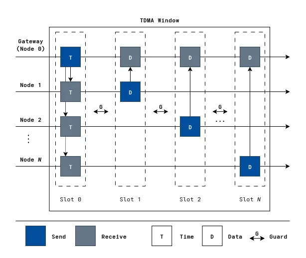
You can think of TDMA as an array of time slots, where each node has a unique ID indexing into the position which it is allowed to transmit. This solves the MAC layer issue of packet collisions at the price of longer latencies when a node actually wants to send something. This isn’t a problem, since the near real-time service quality we are looking to provide only requires data from within the last hour being available. At the start of each TDMA interval, the gateway node broadcasts synchronization packets with its current time (to prevent clock drift between nodes over long-term deployments) and when the next TDMA window starts. The gateway has a satellite transceiver connected to the Iridium satellite network and is responsible for relaying data packets collected by all the nodes in the network through it. These packets get sent to the Iridium satellite network which routes packets to a backend server to be processed and stored.
The strategy outlined in the previous section has gone off more or less without a hitch. I wrote a lightweight RTOS-like “kernel” which handles the scheduling, execution, and pre-emption of all the tasks which the program must accomplish. Across the gateway and peripheral nodes, these include:
- Sampling sensors
- Recording audio
- Signal processing
- Machine learning prediction
- Locally queuing packets to a micro SD card
- Synchronizing TDMA windows
- Sending/receiving data packets over LoRa
- Sleeping until the next task
- Sending data packets over satellite (Gateway only)
I had a lot of fun making this. I got to develop a real embedded systems project with platformio, implement my own reliable network protocol, and spend ample amounts of time debugging the many quirks of embedded systems. Debugging alone could fill its own post. Suffice it to say, I can now track down memory corruption like a bloodhound.
My thesis
Star networks
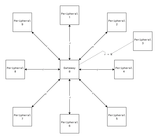
For my master’s thesis, something I thought would be interesting is to research network topologies and protocols for enabling efficient (low-power) multi-hop communication over LoRa. Our current plan for a test deployment involves a star network which has the gateway node at the center and every other node surrounding it. This topology is limited by how far away peripheral nodes can still reach the gateway with their LoRa radios. Essentially, the total area covered by the network is dependent on how far a single link can reach. Let’s say r is the maximum range any two links can communicate. In the figure below, peripheral 3 is outside the circle centered about the gateway with radius r and cannot communicate with it.
Star network limitations
Let’s say in a mountainous environment that we experimentally find r to be about 1.5km. The total area a deployment could reach is then just the area of a circle, πr^2, which would be 7.07 square kilometers. Depending on the size of the area being covered, the area which nodes can communicate with the gateway may not be large enough. Moreovoer, the strength of a radio signal decays quadratically with distance. Trying to maximize the distance nodes are placed from the gateway requires substantially more power during radio transmissions to overcome this. You could deploy multiple star networks independently to overcome the distance problem, but it would be expensive since it requires an extra satellite modem and data plan per network. With each satellite modem costing around $300 and a data plan ranging from $20 - $80 per month for each node, this adds up quick. The preferred solution would be to use other nodes as relays between the sender and gateway. Going back to the example image earier, this would be like if peripheral 3 sent its message to peripheral 1, which then relayed it to the gateway. This is great, because the coverage of a deployment is no longer limited by the distance of a single link. The downside is this is much more complex and hard to test than the current TDMA protocol.
How I worked so far
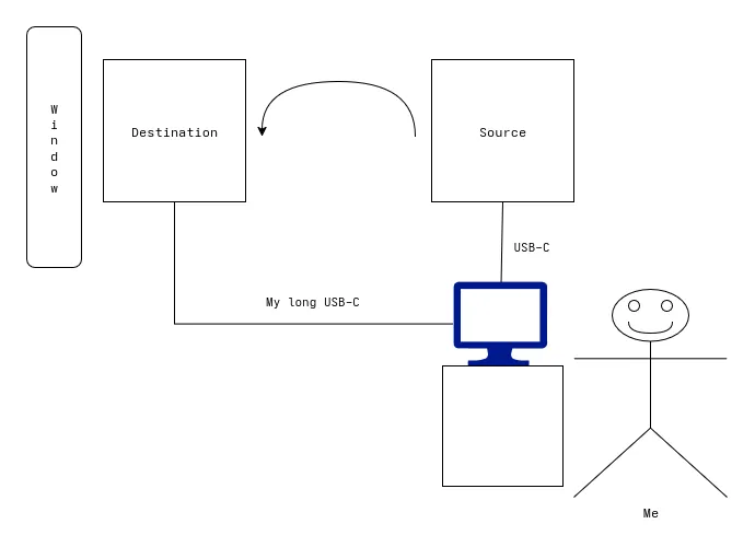
Up to this point, I was able to develop this system from the comfort of my apartment. I tested the TDMA protocol with each node connected to my computer at once. The gateway node would be on the windowsill with a clear(ish) view of the sky (necessary for the satellite) and the peripheral node(s) would be on my coach’s ottoman. An implicit assumption with the star network topology is that nodes can reach the gateway. Whether this is done at their maximum effective range or the distance my longest USB-C cable can reach is irrelevant.
I tested the protocol by making a change to the code and reflashing the board. Compiling these programs takes only a few seconds to do. Uploading them to the device’s flash takes longer- generally about 60-90 seconds. Then, I need to wait for the device to hit one of the scheduled task intervals. Depending on the parameters I built it with, this could be 30 seconds to a couple minutes. With this setup, I can iterate with a write-test-debug cycle about every 2.5-5 minutes. Even though this process is slow relative to something with instant feedback, like testing CSS tweaks in a browser’s dev tools, the absolute time spent waiting is tolerable.
For more complex changes I would write them in an entirely new program which just stages/tests the functionality I am trying to add. This was a very effective strategy for me, since it meant my compile, upload, and wait times for the program to hit the segment of code I am testing were much faster. Additionally, once the feature was implemented and worked in the main program I could keep these smaller programs around as a form of documentation for anyone in the future needing to become acquainted with the components of the system. This doesn’t completely liberate me from slow uploads since I still had to test the full pipeline, but it definitely made things quicker.
The woes of multihop development
I could develop the original TDMA protocol without violating the assumptions of the network since whether nodes were very close or near their maximum distance didn’t really change anything. With a multi-hop protocol, one of the things we must test is that it works when two nodes are truly out of range. Minimally, I would need to test it with three nodes in a straight line with a leaf node communicating through an intermediary node to the gateway. This is the simplest proof of concept that a node can act as a relay.
If the source and destination are within range of each other there isn’t actually a need to communicate through the relay node. You could mimic not being able to hear the source node by adding bit flags to packets which indicate if the packet was sent by the original sender or if it was relayed by an intermediate node. Then, you could have some special handling at the gateway which just ignores any packets marked as coming from the source which don’t also have the relay flag set. This already starts to get hairy since it requires the following being added to the program:
1. Extra metadata in the data packets. This adds overhead to data packets which might not be used for anything in the actual protocol. Packet sizes will be a little bigger and there will need to be extra serialization/deserialization logic.
2. Extra code adding “selective hearing” to the gateway. This is more code which needs to be written for the purpose of staging the program rather than the actual application logic.
Mocking is also just generally prone to not being accurate to what it is supposed to emulate. As more and more mocking is needed to test the code with larger networks, it becomes less likely to work in a real deployment.
You may be asking: “So if mocking a multihop connection isn’t ideal, then why not just do it in real life?”
Simple. It would be a massive pain in the ass.
We have observed communication distances of up to 1.2km between LoRa nodes in urban tests. If I wanted to test the multihop example from earlier IRL I would need to put three nodes over a 2.4km (~1.5 mile) distance! It’s already hard to find a place to test the 1.2km distance so if I wanted to test double that length I would need to go out into the sticks. Even if I did find a suitably sized flat rural location, testing the protocol still requires putting two nodes in areas I cannot easily access them. I’m too paranoid to do this because I would be worried about devices getting damaged or stolen.
One solution is to get two other people to monitor the other boxes during testing. This solves my paranoid “what if” scenarios, but now doing any kind of development requires three times the number of people and even more than three times the number of peoples hours due to the significant communication/travel overhead added. If I needed to make a code change on one of the devices I did not physically have, I would either need to remotely instruct someone on what changes to make (Like pair programming, but without being able to see the code and both hands are tied behind your back. Also, it’s probably cold out and raining because of Murphy’s law.) or physically walk over to do it myself. Even working on the simpler TDMA protocol required lots of trial and error. Doing that with a much harder problem which eats up a magnitude more person hours for each hour of development is not feasible.
Enter: the humble network simulator
What I need is a way to test how this system would work without the overhead of testing it in the real world or the annoyance of complicated staging within the program. Ideally, I could comfortably write code from my desk which looks exactly how it would when deployed on device and quickly simulate a deployment where communications between nodes are masked based on whether they are in range or not. I need a network simulator which allows testing completely arbitrary network topologies/protocols that doesn’t require lots of setup to run. More than just a simulator for demonstraing how existing types of networks work, I need something I can use as a development tool when making my own protocols. I spent some time brainstorming what a “perfect” network simulator would be and came up with the following:
Open source
I generally prefer open source software when possible. It makes me feel warm and fuzzy inside. Also, if I am hopelessly confused and the documentation doesn’t cut it I like being able to crack open the source code and figure it out for myself.
Cross platform
Honestly, this isn’t that big of a deal to me since I would only need it to run on Linux. It’s never a bad thing for software to be able to run on multiple platforms though as long as making it crossplatform doesn’t make any compromises which results in it performing worse.
Easy to use
People can make rollercoasters in excel so the term “right tool for the job” really just means whatever you are most familiar with. That being said, some software is just easier to learn and use than others. The fewer concepts someone needs to learn to get started, the better. An ideal simulator should require minimal knowledge of its implementation to use. It should be easy to install, configure, and intuit the right ways to use the tool. Toward this end, it would be really nice for it to be a one line installation command, use a simple file format people are already familiar with for configuration (JSON, TOML, etc.), and make using the most simple/common cases buttery smooth.
Language agnostic
Many simulators require simulation programs to be written in the language of the simulator (C++ primarily). Some also provide bindings in other languages like Python. This is clearly a limitation for projects which don’t use these languages. Ideally, the interface for communicating with the simulator is agnostic to the langauge used.
Accurate
The simulation should have the capability to provide an accurate simulation of a given network. This means simulating:
- Physical layer communiation
- Delays
- Packet loss
- Bit errors
- Signal shapes
- Signal permeation of physical materials
- Node resources
- Clock rate
- RAM
- Battery
- Mobile nodes
Having the capacity to accurately simulate this is important, but in accordance with being easy to use, the complexity burden should be progressive. For most use cases, a a configuration file should be as simple as node deployments, commands to run the node, and a simple channel configuration detailing expected delays and bit errors. Definitions for common physical links (e.g., Ethernet) should be available out of the box from a central repository of pre-developed links. If a more sophisticated simulation of the physical layer is required, there should be the necessary hooks to use it.
Fast & scalable
The simulator should be able to simulate all the events happening within a network reasonably well within a small timestep. It should be able to simulate many concurrent nodes and be vertically scalable with CPU cores to simulate more nodes at once.
Help development
The simulator should have the developer experience at the forefront. Code should be nearly identical between an actual deployment vs. the version running in simulation. It should have first class support for testing/debugging features:
- Fuzz testing inputs/outputs to probe for crashes with bad inputs
- Detailed simulation logs with the option to replay a simulation (to test changes following a crash, for instance)
- Web interface to visualize protocols
Flexibility
The simulation model should allow simulations to flexibly accommodate arbitrary network topologies/protocols and integrations with other services. This may include hardware-in-the-loop testing or usage with external web APIs.
Community
The project should have ample documentation and a forum page to seek help when debugging issues.
So what are the options?
These are high standards for a single piece of software. This is especially true for open source software which can’t pay people to work on it. While many of the top simulators (ns-3, OMNeT++, Cisco Packet Tracer, Mininet/Containernet, NEMO, etc.) accomplish some of the points on this list, none of them seemed to quite do what I wanted. The more robust simulators have very steep learning curves required to start with them at all. Because many of these simulations require language-specific libraries, simulations require substantial API knowledge just to simulate anything.
This also adds noise to the development process since there are then two divergent copies of the program you must maintain:
1. The one which sets up all the simulation infrastructure using the simulator’s APIs.
2. The production version.
There is both a large upfront cost to learning the simulator APIs and a recurring dual maintenance cost. These both take away time from the actual application development.
My harebrained scheme - The Nexus Network Simulator
By this point I hope I’ve convinced you about some of the deficiencies in existing simulation solutions. In true salesman fashion, I’ll now pitch you on why my ideas are awesome and how the Nexus simulator will be better than all other existing solutions (joke).
First, a word about the name itself. There isn’t any deeper meaning or cool literary/religious allusion. The dictionary definition is: “a connection or series of connections linking two or more things.” I thought this was pretty accurate for a network simulator and the name is catchy.
Anyways, into the architecture!
Programming model & the perfect abstraction
I thought a lot about what the best way to simulate information flowing between nodes in a network is. In doing so, I realized the perfect abstraction has been with us all along- the file. Rather than requiring a special program which imperatively defines/builds the network using complex APIs, I wanted user programs to retain the same structure in the simulation as they would on device.
In my experiences over the summer, pretty much every interface (LoRa radio, satellite, etc.) can be boiled down to reading and writing from some buffer. This is also the exact interface provided by existing file system APIs. For my use case, I would be able to make a tweaked copy of the functions which send/receive from the LoRa radio to read/write to a file when running in the simulator but use the Radiohead library for communicating with the physical radio when running on device. In pseudo-C++, it would look like:
int32_t send(uint8_t buf[], size_t sz) {#ifdef SIMULATOR write("lora", buf, sz);#else radio.send(buf, sz);#endif}This requires some changes to user programs but they are small and don’t require changing the structure of the program.
Clearly, a normal file wouldn’t work since it would have multiple files reading and writing at the same time. I wanted the interface of a file, but not the standard file usage. I was able to accomplish this with a Linux user space file system (FUSE). The file system is viewable by the simulated programs but all interactions are intercepted by the simulation kernel. Each program has a set of UNIX domain scokets used as message buffers for each channel it reads/writes to. When a program makes a request to a channel’s file in the FUSE file system, the process id is collected and the request gets forwarded to the domain socket which may have buffered messages sent by other nodes on the channel. This enables all sorts of tricks where the kernel can give every program its own view on the same channel. To me, this is an elegant solution since it is transparent from the user’s perspective. Anyone familiar with file system APIs already understands the APIs enabling the inter-node communication. The configuration is also very declarative. All you need to specify are the channels and which nodes communicate over them. Packet delays, bit errors, and transmission collisions over shared mediums are handled without any further work by the user.
The configuration language & basic concepts
Something which always irks me is when a project rolls its own configuration language. It’s pretty much always a bad idea. I get that writing a lexer and parser is easy and fun to do, but it’s super annoying for users. Having to learn a new configuration language is cognitive strain not going to development of their application. Unless there are ideas so profound they cannot be expressed in JSON or TOML, I cannot see a good reason for using another language. I chose to build my configuration off TOML for pretty much no reason other than I think it’s prettier to look at than deeply nested JSON.
The configuration has four top-level components:
- Simulation parameters (timestep duration/length/count, random seed, and where to store simulation logs)
- Nodes (descriptions of a class of node which can be deployed in locations)
- Links (descriptions of a physical medium’s behavior)
- Channels (instantiations of a physical link which nodes are connected over)
The configuration is used to setup a FUSE file system which interepts all read and write requests from each simulated protocol running on nodes (each protocol maps 1:1 with a running process and shares the location of the node it is a part of). Yes, the use of FUSE does mean this is only natively supported on Linux. This limits cross-platform support, but Linux features make the design cleaner and more efficient. If this project ever picks up steam in the future, I’ll find ways to achieve this on other platforms.
Here is a more in-depth description of each term used hereon out:
Link: A black box description of the service quality provided by a physical medium. Links described in the TOML file describe the various types of network delays and the probability of bit errors or dropped packets. Link names must be unique in a configuration’s link namespace. Links can choose to inherit from other links to avoid typing the same parameters multiple times when information is almost the same. By default, there is one link in the link namespace titled “ideal”. As the name suggests, this link never encounters errors. There are no delays, packet loss, or bit errors. By default, all links will inherit these characteristics unless explicitly specified for that link or a link which it inherits from.
I’m still working out how to incorporate hooks for more complex physical layer simulations into the kernel. With the existing model, it could be done by adding an extra protocol to nodes which encodes/decodes data being sent/received over a channel. The main protocol would communicate with it over an internal node channel. Effectively, the physical layer simulation would be handled as a middleware program marshaling/unmarshaling data over a channel.
Channel: An instantiation of a link which messages are sent or received by a
protocol. During the simulation, each specified channel will appear as a file in
the nexus simulation directory (~/nexus by default). These come in two
flavors: Shared and Exclusive.
Shared channels are for when there are multiple nodes literally sharing the same channel. For example, carrier-sense multiple access (CSMA) protocols like ethernet would want to be simulated using this. Whenever one node is writing to the channel, others can see it and should avoid writing at the same time.
Exclusive channels are used when the channel is not so much a single physical link but rather a way to group which nodes should be notified upon certain writes. An exclusive channel is analogous to a publisher/subscriber model.
Within the configuration, nodes define which channels they read/write to. This information is used to form a routing table directing writes to a channel into messages sent to nodes subscribed to that channel. These messages are buffered using per-process unix datagram domain sockets after being subject to a “link simulation” where messages get delayed, dropped, or altered before being delivered. Using the FUSE file system, every read/write request by processes started by the simulation kernel is intercepted and serves the response specific to that node. For instance, multiple nodes could be reading/writing to a file with the same location in the file system but get different results based on what that specific node has received.
Node Class: A type of node which is not bound to a deployment location. A node class must define one or more protocols to run per node. All nodes in a node class run the exact same program but can be provided different build arguments. The names for node classes are unique within the node namespace. Deployment locations and additional command line arguments to the runner script are specified within a node class.
Node: A single deployed unit stemming from a node class. The locations of these nodes are used to form the routing table during simulation.
Protocol: A specification for a program which will execute within the context of a single node. For the common case, there will be a single protocol per node (e.g., “main”). For more complex use cases, such as accurately simulating a physical layer or simulating IPC with a daemon process, additional protocols may be defined which run on the same node. Because processes are assuming to run on the same node and are most likely not dropping or scrambling packets, these would likely be specified using internal link names. These protocols take in a command to start them and arguments which should be passed to the command.
Example: multihop over an unreliable link
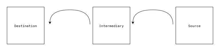
That’s pretty much all the configuration! Provide a TOML file which follows the validation requirements and boom you are done. Here is a configuration file which simulates a multihop protocol over an unreliable link. Also included are the three python files it is running. In this program, a client sends to an intermediary which forwards its message to the server, gets a response, and relays the message back to the client.
[params]timestep.length = 30timestep.unit = "ms"timestep.count = 500seed = 42root = "~/simulations"
[channels]
[channels.client_proxy]link = "unreliable"
[channels.proxy_server]link = "unreliable"
[links]
# .1% chance each bit is corrupted# y = variable as a function of data in `size` units# x = variable as a function of distance in `distance` units (unused here)[links.unreliable.bit_error]rate = "0.001 * y"size = "bit"
# .1% chance each packet gets dropped[links.unreliable.packet_loss]rate = "0.001"
# Transmit 1kb/s[links.unreliable.delays.transmission]rate = 1data = "kb"time = "s"
# Process 1kb/s[links.unreliable.delays.processing]rate = 1data = "kb"time = "s"
[nodes]
[nodes.client]# Deployments optionally take the x, y, z and azimuth, elevation, and roll of# nodes as well as any additional runner args to pass into their protocols.deployments = [{}]internal_names = ["display"]

[[nodes.client.protocols]]
name = "client"runner = "python3"runner_args = ["client.py"]inbound = ["client_proxy", "display"]outbound = ["client_proxy", "display"]
[nodes.proxy]deployments = [{}]

[[nodes.proxy.protocols]]
name = "proxy"runner = "python3"runner_args = ["proxy.py"]inbound = ["client_proxy", "proxy_server"]outbound = ["client_proxy", "proxy_server"]
[nodes.server]deployments = [{}]
[[nodes.server.protocols]]
name = "server"runner = "python3"runner_args = ["server.py"]inbound = ["proxy_server"]outbound = ["proxy_server"]import osimport sysimport time
proxy_path = os.path.expanduser("~/nexus/client_proxy")display_path = os.path.expanduser("~/nexus/display")
counter = 0try: while True: with open(proxy_path, "r+", errors="replace") as proxy: # `display` is just so the final reads from the client with # any bit errors which happened on the return trip from the proxy # get displayed by the simulation kernel's logs with open(display_path, "r+", errors="replace") as display: while msg := proxy.read(): display.write(msg) display.flush() # When ran in the simulation kernel with debug logs on this # displays what is actually received by the intermediary while msg := display.read(): pass msg = f"[{counter}]" proxy.write(msg) proxy.flush() counter += 1 time.sleep(0.25)except Exception as e: print(str(e), file=sys.stderr)import osimport sysimport time
client_path = os.path.expanduser("~/nexus/client_proxy")server_path = os.path.expanduser("~/nexus/proxy_server")
try: while True: with open(client_path, "r+", errors="replace") as client: with open(server_path, "r+", errors="replace") as server: while msg := client.read(): payload = msg + "[Proxy 1]" server.write(payload) server.flush() while msg := server.read(): payload = msg + "[Proxy 2]" client.write(payload) client.flush() time.sleep(0.25)except Exception as e: print(str(e), file=sys.stderr)import osimport sysimport time
proxy_path = os.path.expanduser("~/nexus/proxy_server")
try: while True: with open(proxy_path, "r+", errors="replace") as proxy: while msg := proxy.read(): payload = msg + "[Server]" proxy.write(payload) proxy.flush() time.sleep(0.25)except Exception as e: print(str(e), file=sys.stderr)Shortcomings
I believe this model for a simulation is substantially easier to work with and is more directly transferrable to an application. Despite this, there are definitely some hurdles to overcome.
1. Finegrained timing
While Nexus already simulates delays of links, something I cannot control are the operating system’s scheduling decisions. As it is now, each program corresponding to a node’s protocol gets started and is ran with next to no supervision by the kernel itself. This problem is somewhat alleviated by the fact that any reads/writes to channel files does get synchronized at the end of each timestep but may pose issues for repeatability of very particular timing issues. I do intend to add support for specifying the computing resources each node has (e.g., Clock rate and RAM) with cgroups to make relative process timings more accurate to an actual deployment.
2. Ecosystem
Existing simulators have been around for a long time and have massive amounts of support. It’s hard to match the amount of code which has been written for highly accurate network simulators as in something like ns-3. I hope that with the flexible design of Nexus I may be able to incorporate existing open-source software to quickly amass a large library of supported physical layer simulations and network protocols.
Wrapping up
For only standing at about 4,000 lines of Rust code this is already a fairly robust simulator! There is much more I plan to add in the future, but so far I’m pretty proud of the features which are there:
- Charming CLI
- Configuration language
- FUSE filesystem for intercepting reads/writes
- Discrete-event simulation kernel
- Routing table
- Link simulation
- Simulation playbacks
- Simulation of both shared and exclusive channels
To give an idea of what’s to come, here is the current state of my “todos” document I keep for this project:
- Node resource simulation with cgroups
- Signal shape simualation (cone, LOS w/ bounding box, adjacent (vertical horizontal), omnidirectional, etc.)
- Energy modeling
- Battery modeling
- Energy scavenging
- Node shutoff & threshold restarts
- Web interface
- Drag & drop interface for building config file
- Visualize protocol execution
- Mobile node simulation
- Predefined paths
- Dynamic paths
- Environment simulation
- Import real terrains?
- Material type & signal penetration simulation?
- 6DOF
- Project website
- Forums
- Docs
- Package repository for predefined links
As you can see, there is lots to do! I plan to provide routine updates on the status of the CIROH project and my thesis as new milestones are hit (and when I have the time to write about it).
If you’re still here, thanks for sticking around! If you have any questions, comments, or suggestions feel free to email me at jordanbourdeau03@outlook.com.
Cheers!
- Jordan